
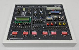
Logic Lab Trainer LLT-900Description
- Description
Description
Features
• The LLT-900 Logic circuit Lab offers a unique entry into the world of microelectronics.
• The system combines simple, easy to use, logic gates with a versatile solderless breadboard area.
• By using the clearly marked built-in logic gates, students new to digital electronics can implement logic circuits in a matter of seconds.
• As confidence grows the student will naturally progress to using more complex logic integrated circuits on the undedicated breadboard area.
• This unique approach enables the unit to be used by the absolute beginner, yet it may also be usefully employed in advanced project work.
• The many outstanding features of the Logic Lab, combined with its ease of use and robust housing, make it the first choice for those wishing to introduce students to logic gates for the first time
Specification
1. Logic Gates: 60 built-in logic gates comprising:
• Eight dual-input AND gates
• Eight dual-input OR gates
• Eight dual-input NAND gates
• Eight dual-input NOR gates
• Eight dual-input XOR gates
• Eight dual-input XNOR gates
• Eight single-input NOT gates
• Two dual-input J-K Flip-Flop
• Two dual-input D Flip-Flop
2. Onboard Components:
• Two Transistors
• Three Diodes
• Five Resistors
3. DC Power Supply
• Fixed Output: +5V/0.5A, -5V/0.5A, +12V/0.5A, -12V/0.5A
• Variable Output: -0V to -23V/0.5A, +0V to +23V/0.5A
4. Two Digit Seven Segment Display
Numerical designs and resultant display Truth Table


Segment Identification

5. Logic Switches
• Provide two sets of pulse output &
6. Pulse Generator
• 1sec (1Hz), 0.1sec (10Hz) and 0.01sec (100Hz) 3 kind of time interval
7. Data Switches
• Eight Bits robust debounced HI/LO slide switches
• TTL/CMOS level selection
8. Logic Indicators
• Eight Bits LED logic indicators
9. Pulse Switches
• Two (2) 80µs Pulse Single Shot (Positive Pulse, Negative Pulse)
10. Solderless Breadboard
• 1896 interconnected tie points, accepting all DIP devices, components with leads and solid wires of AWG 22 (0.3 to 0.8mm)
EXPERIMENTS COVER
The LLT-900 comes with softcopy experiments manual to cover the following experiments topics:
Chapter 1: Basic practice of the TTL logic
• Experiments 1: NOT Gate Experiments
• Experiments 2: AND Gate Experiments
• Experiments 3: OR Gate Experiments
• Experiments 4: NAND Gate Experiments
• Experiments 5: NOR Gate Experiments
• Experiments 6: EXCLUSIVE OR Gate Experiments
• Experiments 7: OPEN COLLECTOR Gate Experiments
Chapter 2: Basic Practice Of the CMOS Logic
• Experiments 1: TTL and COMS interface practice use the same power supply.
• Experiments 2: TTI and COMS interface operate under different power supply.
• Experiments 3: CMOS gate practice
• Experiments 4: Pull up NOT GATE to NOR GATE operation practice.
• Experiments 5: Pull down NOT GATE to NAND GATE.
The LLT-900 is shipped with:
• Comprehensive CD softcopy version instruction manual and experiments manual
• AC 3 pin power cord (UK Type)
• Power Supply: 240VAC, 50Hz (Fused Protected)
• Dimensions: 310 x 260 x 90mm (W x D x H)
• Weight: 3.5 kgs
Note: Due to products continuous development process, layout and specification may change without prior notices.