
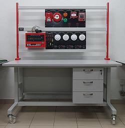
Fire Alarm Control Trainer (Show Case Type) CE-30-01-04-06Description
- Description
Description
Description
Fire Alarm Control Trainer CE-30-01-04-06 has been specially designed for courses of building services, mechanical & electrical engineering, plant engineering, chemical engineering, marine & mining engineering etc.
This Fire Alarm Control Trainer is the scale down automatic fire detection alarm system installed in buildings. It is design to educate student the functional aspect of this fire protection system.
This module unit can be activated to simulate the activation of the whole fire protection system real time.
This control panel works on 24VDC and is operated by 240VAC 50Hz power supply. In the event of power failure, back-up supply is available from stand-by battery pack. Unit will automatically switch to battery power when AC supply is interrupted therefore integrity of the system is maintained at all time. It will automatically revert to AC power when normal power supply is restored. At the same time back-up battery pack will automatically be re-charged to the regular level.
The show case panels come in various ranges from 4 zones as standard. Larger zones capacities are available to user’s specification. Build-in mimic diagram with L.E.D indicator are located on the panel to show the location of the alarmed zone. It accepts a wide variety of detectors and sounding devices with line supervised output provided for zone and alarm bell circuits. Optional fire pump sets and auxiliary panel status can be monitored remotely.
Experiments Cover
- Demonstrate the process of fire alarm control panel activation.
- Provides real time simulation and activation of the fire alarm control system.
- Able to determine the actual course of activation from the control panel and safety procedure to be taken.
Features
- Simple layout with easy to operate features.
- Simple operation.
- Self contained – required only electrical supply (240VAC, 50Hz)
- User friendly and easy to operate.
- Used standard devices and components which are readily available at any outlet specialized in fire protection system.
- Built-in standby batteries in case of power supply failure during demonstration.
- Easy to maintain – can be repaired and service by any competent fire technician.
It consists of the followings:-
- 1 Unit 4 Zones Fire Alarm Control Panel C/W Built In Charger
- 2 Units Standby Battery 12V/2.3Ah Sealed Lead Acid Gel
- 1 Unit Smoke Detector
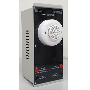
- 1 Unit Heat Detector
- 1 Unit Manual Alarm Button (Breakglass)
- 1 Unit Alarm Bell
- 2 Units Flash Light (Red & Yellow)
FIRE ALARM CONTROL PANEL CE-30-01-04
Specification
- Main & D/C On Indication
- Main Fail Indication
- Battery Fail Indication
- Charger Fail Indication
- Bell Line Fail Indication
- Zone Fire, Fault & Isolate Indication
- Evacuate Switch & Indication
- Buzzer Isolate Switch & Indication
- Bell Isolate Switch & Indication
- Fire Station Isolate & Indication
- Auxiliary Trip Isolate Switch & Indication
- Test Zone Alarm, Fault & Isolate Switch
- Master Reset Push Button Switch
Technical Data:
- Power supply input: 240VAC, 50Hz
- Charger: Auto / Trickle
- End of line: 8K2 Ohms
- CMS output: N/O Contact
- Operating / System: 24V DC
- Charging rate: 300mA / 2.5A (Boost)
- Auxiliary output: 24V, 1A
- Current spec: Standby Mode – Master: 75mA, per zone c/w detector: 5mA
- Alarm Mode – Master: 140mA, per trigger zone: 70mA
- Output devices (typical): 200mA, per bell: 30mA
Student Courseware
- Instruction Manual consists of circuit/wiring diagram, devices information, experiments and operation of the system in softcopy CD Format.
Note: Due to products continuous development process, layout and specification may change without prior notices.