
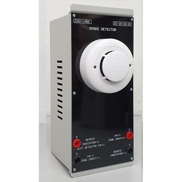
Heat Detector CE-20-02-02Description
- Description
Description
The detectors are photo-electronic detector uses a state of-the-art optical sensing chamber. This detector is designed to provide open area protection and to be used with most conventional fire alarm panel.
Two LEDs on each detector provide local 360° visible alarm indication. They flash every six seconds indicating that power is applied and the detector is working properly. The LEDs latch on in alarm. LEDs will be off when a trouble condition exists indicating that the detector sensitivity is outside the listed limit. The alarm can be reset only by a momentary power interruption.
The detector that initiated the alarm condition will have its red LED and relays latched until reset by panel.
Heat detector and smoke & heat detector combine a photo electronic sensing chamber and a temperature heat detector.
o Operating Voltage: 9 to 28 VDC Volts Non-polarized
o Standby Current: ≤120µA@24VDC
o Maximum Alarm Current (LED on): ≤15mA@24VDC
o (1K Ohm current-limiting resistance)
o Operating Humidity Range: ≤95%RH (40°C±2°C) Relative Humidity, Non-condensing
o Operating Temperature Range: -10°C to 50°C (14°F to 122°F)
o Smoke Alarm Sensitivity: 1.06±.26%FT
o Fix temperature Alarm: 57°C (135°F) A1R
o Rate of rise Alarm: 7.1°C/5S A1R
o Height: 48.2 mm installed in Base
INSTALL THE DETECTOR HEAD
1. Align detector head alignment mark line with the base’s start alignment mark line.
2. Push the detector head into the base while turning it clockwise to secure it in place.
3. Do not install the detector head until the area is thoroughly cleaned of construction debris, dusts, etc.
4. After all detectors have been installed, apply power to the control panel.
WARNING: The detector is only connected to conventional fire alarm panel, NOT permit to connect DC9-28V power supply directly to terminal IN+, IN-
Note: Due to products continuous development process, layout and specification may change without prior notices.