
Fire Alarm Control System Trainer (Modular Type) CE-30-04-16Description
- Description
Description
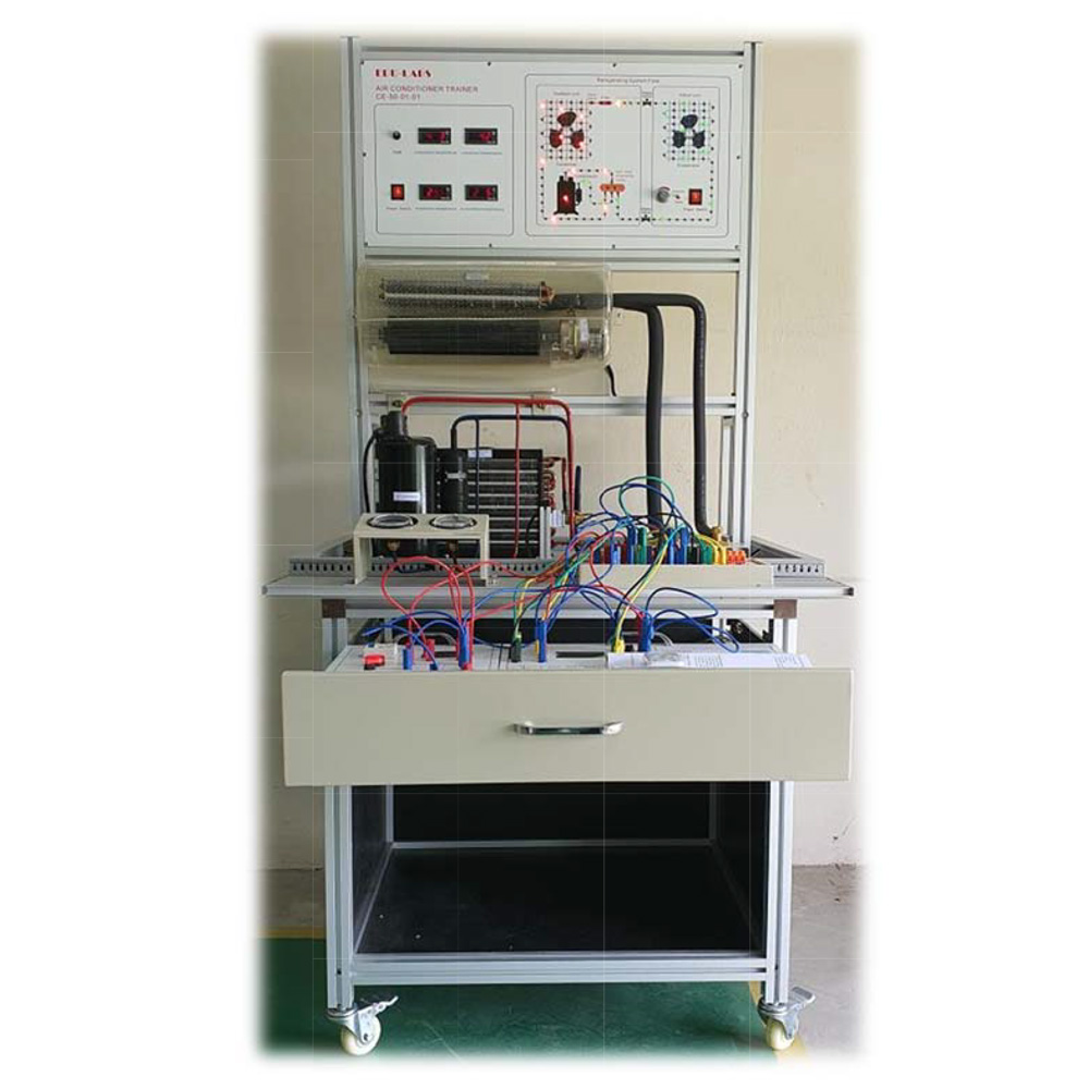
Fire Alarm Control System Trainer CE-30-04-16 has been specially designed for courses of building services, mechanical & electrical engineering, plant engineering, chemical engineering, marine & mining engineering etc.
This system are designed in modular type where student are able to do the experiment by connecting the modules by using safety test leads set and able to activated and simulate of the whole fire protection system real time.
This control panel works on 24VDC and is operated by 240VAC 50Hz power supply. In the event of power failure, back-up supply is available from stand-by battery pack. Unit will automatically switch to battery power when AC supply is interrupted therefore integrity of the system is maintained at all time. It will automatically revert to AC power when normal power supply is restored. At the same time back-up battery pack will automatically be re-charged to the regular level.
The panels come in various ranges from 4 zones as standard. Larger zones capacities are available to user’s specification. Build-in mimic diagram with L.E.D indicator are located on the panel to show the location of the alarmed zone. It accepts a wide variety of detectors and sounding devices with line supervised output provided for zone and alarm bell circuits. Standard fire pump sets and auxiliary panel status can be monitored remotely.
Experiments Cover
- Demonstrate the process of fire alarm control panel activation.
- Provides real time simulation and activation of the fire alarm control system.
- Able to determine the actual course of activation from the control panel and safety procedure to be taken.
Features
- Modular Type Design Plug & Play format
- Simple layout with easy to operate features.
- Simple operation.
- Self contained – required only electrical supply (240VAC, 50Hz)
- User friendly and easy to operate.
- Used standard devices and components which are readily available at any outlet specialized in fire protection system.
- Built-in standby batteries in case of power supply failure during demonstration.
- Easy to maintain – can be repaired and service by any competent fire technician.
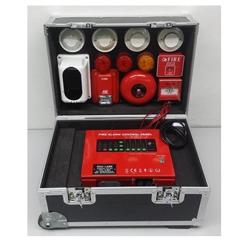
This Fire Alarm Control Trainer is the scale down automatic fire detection alarm system installed in buildings. It is design to educate student the functional aspect of this fire protection system.
It consist of the followings Experiments Modules :-
- 1 unit 4 zones fire alarm control panel c/w built in charger
- 2 units Standby battery 12V/2.3Ah
- 1 Unit Alarm Bell
- 1 Unit Horn Strobe
- 2 Unit Smoke Detector
- 2 Units Heat Detector
- 2 units Flash Light
- 2 unit Manual Call Point (Breakglass)
- 1 unit Magnetic Contact Sensor
- 1 unit PIR Motion Detector
- 1 Set Safety Test Leads Set
- 1 unit Experimental Frame 2 Layer
- 1 unit Workbench Table
| FIRE ALARM CONTROL PANEL CE-20-01-04 | |||||||||
 |
|||||||||
| Specification
o Main & D/C on indication o Main fail indication o Battery fail indication o Charger fail indication o Bell line fail indication o Zone fire, fault & isolate indication o Evacuate switch & indication o Buzzer isolate switch & indication o Bell isolate switch & indication o Fire station isolate & indication o Auxiliary trip isolate switch & indication o Main on / off switch o Test lamp switch o Test zone alarm, fault & isolate switch o Test battery push button switch o Master reset push button switch |
Technical Data
4 zones fire alarm control panel c/w built in charger
o Power supply input : 240V AC 50Hz o Charger : Auto / Trickle o End of line : 8K2 Ohms o CMS output : N/O Contact o Operating / System : 24V DC o Charging rate : 300mA / 2.5A (Boost) o Auxiliary output : 24V, 1 Amp o Current spec : Standby Mode – Master: 75mA, per zone c/w detector: 5mA o Alarm Mode – Master : 140mA, per trigger zone: 70mA o Output devices (typical) : 200mA, per bell: 30mA o 2 units Standby battery 12V/2.3Ah |
||||||||
| SMOKE DETECTOR CE-20-02-01 | |||||||||
|
|
The detectors are photo-electronic detector uses a state of-the-art optical sensing chamber. This detector is designed to provide open area protection and to be used with most conventional fire alarm panel.
Two LEDs on each detector provide local 360° visible alarm indication. They flash every six seconds indicating that power is applied and the detector is working properly. The LEDs latch on in alarm. LEDs will be off when a trouble condition exists indicating that the detector sensitivity is outside the listed limit. The alarm can be reset only by a momentary power interruption. The detector that initiated the alarm condition will have its red LED and relays latched until reset by panel. Heat detector and smoke & heat detector combine a photo electronic sensing chamber and a temperature heat detector.
o Operating Voltage: 9 to 28 VDC Volts Non-polarized o Standby Current: ≤120µA@24VDC o Maximum Alarm Current (LED on): ≤15mA@24VDC o (1K Ohm current-limiting resistance) o Operating Humidity Range: ≤95%RH (40°C±2°C) Relative Humidity, Non-condensing o Operating Temperature Range: -10°C to 50°C (14°F to 122°F) o Smoke Alarm Sensitivity: 1.06±.26%FT o Fix temperature Alarm: 57°C (135°F) A1R o Rate of rise Alarm: 7.1°C/5S A1R o Height: 48.2 mm installed in Base
INSTALL THE DETECTOR HEAD 1. Align detector head alignment mark line with the base’s start alignment mark line. 2. Push the detector head into the base while turning it clockwise to secure it in place. 3. Do not install the detector head until the area is thoroughly cleaned of construction debris, dusts, etc. 4. After all detectors have been installed, apply power to the control panel. WARNING: The detector is only connected to conventional fire alarm panel, NOT permit to connect DC9-28V power supply directly to terminal IN+, IN- |
||||||||
| HEAT DETECTOR CE-20-02-02 | |||||||||
|
|
The detectors are photo-electronic detector uses a state of-the-art optical sensing chamber. This detector is designed to provide open area protection and to be used with most conventional fire alarm panel. Two LEDs on each detector provide local 360° visible alarm indication. They flash every six seconds indicating that power is applied and the detector is working properly. The LEDs latch on in alarm. LEDs will be off when a trouble condition exists indicating that the detector sensitivity is outside the listed limit. The alarm can be reset only by a momentary power interruption. The detector that initiated the alarm condition will have its red LED and relays latched until reset by panel. Heat detector and smoke & heat detector combine a photo electronic sensing chamber and a temperature heat detector.
o Operating Voltage: 9 to 28 VDC Volts Non-polarized o Standby Current: ≤120µA@24VDC o Maximum Alarm Current (LED on): ≤15mA@24VDC o (1K Ohm current-limiting resistance) o Operating Humidity Range: ≤95%RH (40°C±2°C) Relative Humidity, Non-condensing o Operating Temperature Range: -10°C to 50°C (14°F to 122°F) o Smoke Alarm Sensitivity: 1.06±.26%FT o Fix temperature Alarm: 57°C (135°F) A1R o Rate of rise Alarm: 7.1°C/5S A1R o Height: 48.2 mm installed in Base
INSTALL THE DETECTOR HEAD 1. Align detector head alignment mark line with the base’s start alignment mark line. 2. Push the detector head into the base while turning it clockwise to secure it in place. 3. Do not install the detector head until the area is thoroughly cleaned of construction debris, dusts, etc. 4. After all detectors have been installed, apply power to the control panel.
WARNING: The detector is only connected to conventional fire alarm panel, NOT permit to connect DC9-28V power suply directly to terminal INp+, IN- |
||||||||
| FIRE ALARM BELL CE-20-04-01 | |||||||||

|
Working Principle
Fire alarm internally by a 24V DC motor driven by the crankshaft and connecting rod bells, no relays work, work current, high reliability. Function Fire alarm for supporting specific products and linkage fire alarm systems, when the system recognizes fire broke out by linkage control equipment to the scene.
|
||||||||
| HORN STROBE (3 TYPE BUZZER SOUND) CE-20-05-01 | |||||||||

|
The strobe horn fire alarm is a kind of terminal device for alarm; it is used for the sound & light alarm when the fire happens.
Feature: Adopt the two-wire or the four-wire system wiring method and the main line end receives two main lines, no polarization; and connect the power end to DC24V power line. o Temperature Range: -10~+50℃ o Humidity Range: ≤95% RH o Operating Voltage: DC12-DC24 No-polarized o Working Current : ≤60 mA o Flash Intensity: ≥1.2 WS o Flash Period: ≤1.0 S o Alarm Sound: ≥100 dB o Flash Light Lifespan: ≥40000 TIME o Alarm Sound Type: 3 Type sounds: 1. Ambulance Sound 2. Police Car Sound 3. Fire Truck Sound |
||||||||
| MANUAL CALL POINT (I) (PANIC GLASS BREAK EMERGENCY SWITCHES) CE-20-06-01 | |||||||||

|
Conventional manual call point is designed to be use with an intelligent two-wire control system. If it is pressed after a fire is manually confirmed, an alarm signal may be sent to a fire alarm control system which will, after receiving the alarm signal, display the equipment status of the manual call points. When the manual call point is operating normally, the red indicator will blink; when there is a fire alarm, it will remain lit.
o Main Voltage Zone 24V or 12V o Operating current monitoring status≤20uA, alarm status≤15mA o Wiring The promise of two bus system(Zone +, Zone -) o Protection class IP30 o Indicator Red alarm indicator flashes when it is under normal o condition, press the manual button lit work o Environmental Class A temperature range: -5 to 40°C (23~104°F) o Humidity: 5 to 95% RH, non-condensing Work condition Normal: Green light blink. Alarm: Red light normally on and green light off. |
||||||||
| MANUAL CALL POINT (II) (PANIC GLASS BREAK EMERGENCY SWITCHES) CE-20-06-02 | |||||||||
|
|
o Operating Voltage Range: 9~28VDC Volts
o Alarm Current 45 mA @ 24 VDC o Operating Humidity Range: 10% to 93% Relative Humidity, Non-condensing o Operating Temperature Range: -10°C to 50°C (14°F to 122°F) OPERATION The manual call points provide a textured finger-hold area that includes Braille text. In addition to PUSH IN and PULL DOWN text, there are arrows indicating how to operate the station, provided for non-English-speaking people. Pushing in and then pulling down on the handle activates the normally-open alarm switch. Once latched in the down position, the word ACTIVATED” appears at the top in bright yellow, with a portion of the handle protruding at the bottom as a visible flag. Resetting the station is simple: insert the key, twist one quarter-turn, then open the station’s front cover, causing the spring-loaded operation handle to return to its original position. The alarm switch can then be reset to its normal (non-alarm) position manually (by hand) or by closing the station’s front cover, which automatically resets the switch. |
||||||||
| FLUSH LIGHT CE-20-03-01 | |||||||||

|
Description
The product is fire flashing lights, a fire alarm device, generally used for more staff in public areas. In the event of an emergency situation is controlled by the alarm controller to trigger flashes, warning people to fire. Working Principle Flash fire inside a 24V DC LED lights, 24V DC triggered by flashing LED lights set to issue an alarm signal, current, long life, high reliability. Function Fire flash matching specialty products for fire alarm and linkage system, when the system confirms the fire broke out by linkage control device, an alarm signal to the scene. |
||||||||
TEST LEAD SETS CE-30-15-03 |
|||||||||

|
o The set consists of stackable test lead set and 2 type bridging plug set in 5 different coded colors and lengths chosen to allow the realization of all experiment manual.
o Leads are capable of 5A current safety plugs. o Stackable Terminal Socket & Plug (4mm) o 19mm Bridging Plug Set o 19mm Bridging Plug Set (Stackable)
|
||||||||
| EXPERIMENTAL FRAME (2 LAYER) CE-30-16-02-02 | |||||||||
 |
|
||||||||
| WORKBENCH TABLE TOP CE-30-16-01-03D | |||||||||
 |
· Length: 1500mm · Width: 800mm · Height: 800mm
|
||||||||


Student Courseware
- Instruction Manual consist of circuit/wiring diagram, devices information, experiments and operation of the system in hardcopy & softcopy CD Format.
Note: Due to products continuous development process, layout and specification may change without prior notices.