
8051 Microcontroller Trainer MCT-8051Description
- Description
Description
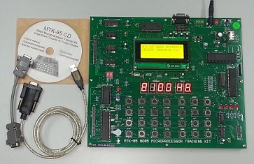
The 8051 microcontroller trainer is designed specifically for educational, institutes and individuals who are interested in 8051 microcontroller. It includes a Microcontroller Module with I/O ports Module, DC Power Supply Module and 9 standard application modules & 2 optional application modules. Come with complete software package for programming, source code editing, assembling, compiling, program writing.
Features:
- 8051 Integration Development Environment Program.
- Display the 8051 internal architecture.
- Edit, Assemble, Compile, Download, and program running of source file.
- C-language, Assembly language source code debugging function.
- Program trace, Break function.
- Code memory disassemble function.
- 8051 Register, internal/external memory dump and editing function.
- Program scroll display function.
- Pop-up menu display.
- Program stop function by “ESC” key.
- 8751, 87C51, 89C51, 80C52 writing function.
- Use to keyboard and mouse.
- I/O experiment by C-Language.
- Various I/O port experiment.
- Dot Matrix experiment.
- DC motor, Step motor experiment by D/A Converter.
- Volt meter experiment by A/D Converter.
- Various command function.
- Sound experiment.
- 8751/89C51 Read/Write/Verify/Erase function.
- Experiment use to Micro controller test units.
- Keyboard function.
- LCD display function.(16 X 2 Line)
- +5V, -5V, +12V, -12V (Free Voltage) Power (240V)
Extra Features
- Standard 87C52 CPU clocked at 22.1184 MHz
- 50 I/O lines with 10 x 5 rows of 2mm brass socket & Turn-pin input/output ports
- 32k SRAM, program variables and code (24k usable for code download)
- 30k Flash ROM, non-volatile program storage and data logging
- High speed baud rates: 115200, 75600, 38400, etc. All standard baud rates are supported (except 300 baud)
- Display port, works with standard character-based LCDs such as 16×2 LCD display and 20 x 2 LCD Display
- Eight LEDs, controlled by 8 dedicated I/O lines (not shared with the 50 I/O lines)
- Bus expansion with 4 chip select signals, for adding UARTs, A/D converters and other bus-based peripheral chips.
- EDUMON monitor program for easy code development without additional equipment.
The Main Frame
- The 8051 microprocessor board is built-in to the main frame. This will allow students to have visibility of the 8051 microcontroller board with minimum access to the board.
- 10 x 5 rows of 2mm brass socket & Turn-pin input/output ports are provided.
- DC power supplies of +5V(two each), -5V(two each), +12V(two each), -12V(two each) and GND (two each) are provided.
- The reset/restart button for the microcontroller should be easily accessible on the main trainer.
- Computer interfacing connectors of 8051 board are available.
- Input Voltage: AC 240V ; 50Hz
Accessories
- Power cord with a 13A fused mains plug at one end and a straight socket at the other.
- Relevant sets of 8051 technical data and programming manuals.
- RS-232 interfacing cable.
- Technical information, instruction manuals and circuit diagrams for the 8051 Microcontroller Trainer and Application Modules (including soft copy).
Application Modules
The set comprises 9 built in application modules which attached to the main frame of the 8051 microcontroller trainer unit. The application modules powered from the 8051 microcontroller trainer’s built-in power supply module.
Functional details of the Application Modules :
Module 1 : 8 Bits Data Display Module
This module consists of 8 input sockets and 8 buffers driven LEDs. It is used for monitoring the status of the each output port bit of the main frame.
Module 2 : 8 Bits Switch Input Module
This module consists of 8 toggle switches and 8 buffer driven output sockets. It is used for input of data to the input port of the main frame.
Module 3 : 7 Segment Display Module
This module consists of two 7-segment displays. The display is driven by a BCD to 7-segment driver IC through 2 multiplexing transistors.
Module 4 : Digital To Analog Converter Module
This module consists of an 8-bit D/A converter IC. Its output drives an inverting op amp with variable amplification factor.
Module 5 : DC Motor Control Module
This module consists of a small DC motor, 2 relays for direction control and an amplifier circuit for feeding PWM power to the DC motor.
Module 6 : Stepper Motor Control Module
This module consists of a 4-phase unipolar stepper motor driven through a buffer IC. 4 LEDs are connected to the stepper motor terminals so that phase status can be observed (at low speed stepping only).
Module 7 : Keypad Module
This module consists of a 12 key keypad wired up in 3 x 4 matrix. It is an input device for the main frame.
Module 8 : Dot Matrix Display Module
This module consists of dot matrix Display. They are driven by buffers matrix.
Module 9 : LCD Display Module
Consists of a LCD panel (2 x 16 characters). Supply + 5V DC and ground terminals
Module 10 : Trigger Sensors And Alarm Circuit Module (Optional)
This module consists of 4 photo-coupled input devices and 2 transistors driven devices, a buzzer and a lamp.
Module 11 : Car Park System Application Module (Optional)
This module consists of 2 sets of Infrared detectors, 2 motor driven gates, and four 7-segment displays. This module is designed for testing automatic car-park system software on a small scale.
Interface Software Programs & Source Code
This is the complete monitor code provided on the board:
- edumon.asm – EDUMON Configured For This Board
- extra.asm – Disassembler, Memory Editor and Single-Step Utilities
- Intel Hex For 87C52
Softcopy in CD-ROM format and manual to be provided.