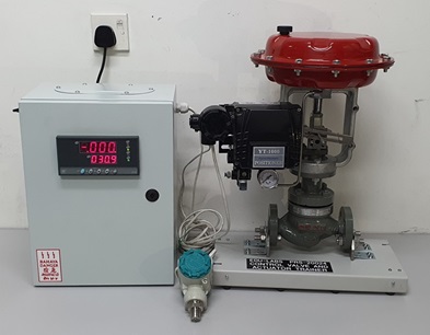
Control Valve And Actuator Trainer PRS-20024Description
- Description
Description
The training equipment are integrated with latest Industrial Revolution 4.0 (IR4.0) technology features.
Control valves are key components of process engineering systems. They act as an actuator and create a link between the controller and the system. Control valves are generally used for regulating flows of gases or liquids. Optimum control loop design depends on a sound knowledge of control valve behaviour as well as knowledge of the controlled system response is significant in Marine Engineering.
TECHNICAL SPECIFICATION
1. PID CONTROLLER PANEL
a. Signal Generator: 4–20mA Output
b. 24VDC Power Supply
c. 4-20mA Input
2. PNEUMATIC CONTROL VALVE MODULE
a. Actuator
i. Type: Multi-spring diaphragm actuator
ii. Action type: Direct action, reverse action
iii. Diaphragm material: NBR rubber reinforcing polyester fabric
iv. Spring range: 20~100KPa
v. Supply pressure:0.4~0.5MPa
b. Pneumatic Control Valve
i. Type: Single Acting Pneumatic Valve
ii. Output: 4-20mA
c. Valve Body
i. Type: Single Seat
ii. Nominal Diameter: DN15
iii. Nominal Pressure: PN16
iv. Connection: Flange
v. Sealing Surface: PN16
vi. Connection Size: 1/2″
vii. Flange Material of Construction: Cast Iron (Body)
d. Positioner
i. Electro-Pneumatic Type
ii. Supply Pressure: 1.4-7kgf/cm2
iii. 4-20mA Input signal
iv. 4-20mA Output signal
v. Air Filter
vi. One Way Check Valve
vii. Input Pressure Gauge
viii. Control Pressure Gauge
3. PRESSURE TRANSMITTER MODULE
a. 18-36VDC Power Supply
b. 4-20mA Output
c. 0-1MPa
4. SILENT TYPE AIR COMPRESSOR (OPTIONAL)
a. Power: 550W
b. Speed: 1300RPM
c. Pressure: 8.8 Bar
d. Exhaust Volume: 60L/min
Note: Due to products continuous development process, layout and specification may change without prior notices.


