
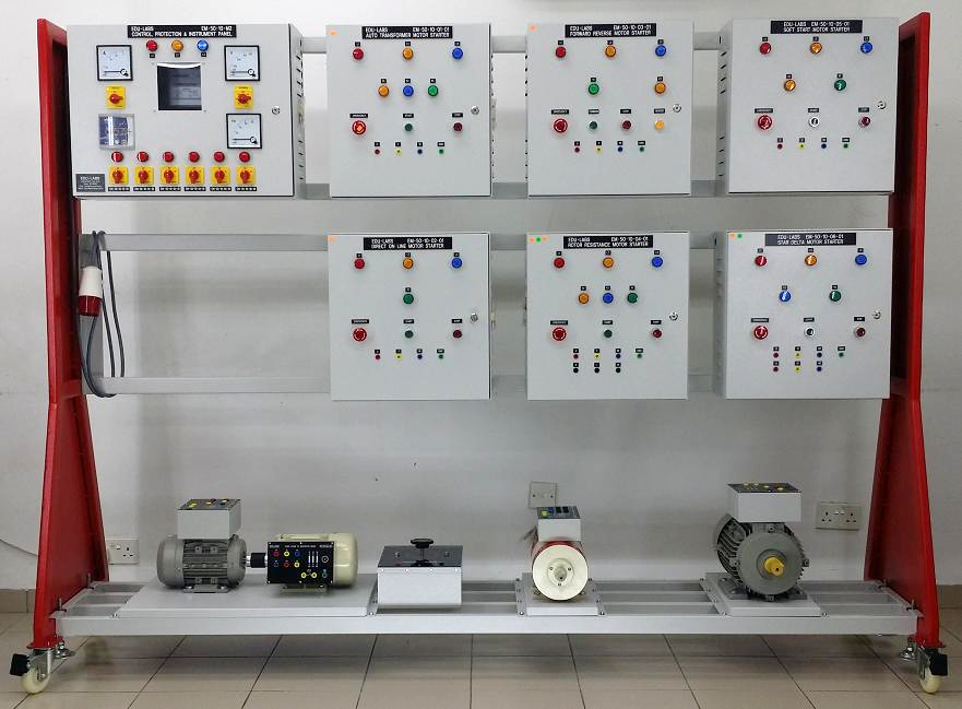
Motor Control Starter Panel EM-69232Description
- Description
Description
1.0 GENERAL SPECIFICATION
1.1 This motor control panel are designed to start, operate and control the electrical motor
1.2 All of the standard controls, protections and instruments are containing IEC standards and safety (include cable connection to terminal)
1.3 All equipment/components must be mounted on panel box and without wire (for student self-wiring practice)
1.4 All front panel compartments/parts are clearly labeled marked to ensure easy reference and better understanding of the internal circuitry and/or components functions
1.5 All terminal connections and terminations are clearly numbered, marked and labeled
1.6 Marking: Engraved legends
1.7 Mounting: Equipment is mobile with heavy duty locking swivel castor wheel
1.8 Panel Box: Heavy sheet steel metal console finished by baked epoxy powder coating
1.9 Provision for external connection via safety type terminal socket on terminal box
1.10 Approx. size: 600 (L) x 400 (W) x 1500 (H) mm
Suruhanjaya Tenaga Syllabus Chargeman Category A0
Module: Motor and its starter
a) Types of motor, usage, difference and movement
b) Maintenance, damage detection and repair
c) Starter including characteristics of protection
2.0 TECHNICAL SPECIFICATION
2.1 Front Panel complete with accessories specification:
2.1.1 1 unit Analogue AC Ammeter: 0 – 40 A
2.1.2 1 unit Analogue AC Voltmeter: 0 – 500 Vac
2.1.3 1 unit Selector Switch for Auto-Off-Manual
2.1.4 1 unit Ammeter Selector Switch
2.1.5 1 unit Voltmeter Selector Switch
2.1.6 2 units Selector Switch On-Off for Trip function
2.1.7 1 unit Mushroom Head Emergency Stop Button
2.1.8 2 unit Green Push Button Switch (2 x Start)
2.1.9 2 units Red Push Button (2 x Stop)
2.1.10 1 unit Green Push Button (1 x Forward)
2.1.11 1 unit Green Push Button (1 x Reverse)
2.1.12 3 units LED Pilot Lamp (Red/Yellow/Blue) – Main Phase Lamp
2.1.13 5 units Red LED Pilot Lamp (2 x Stop, 2 x Trip and 1 x Emergency Switch)
2.1.14 2 units Green LED Pilot Lamp (2 x Run)
2.1.15 1 unit Blue LED Pilot Lamp (1 x Forward)
2.1.16 1 unit White LED Pilot Lamp (1 x Reverse)
2.1.17 2 units Amber LED Pilot Lamp (1 x Auto and 1 x Manual)
2.2 Internal panel complete with accessories specification:
2.2.1 1 unit Molded Case Circuit Breaker 60 A 3 Pole
2.2.2 3 units Miniature Circuit Breaker 32 A 3 Pole
2.2.3 1 unit Miniature Circuit Breaker 6 A 2 Pole
2.2.4 3 units Miniature Circuit Breaker 6 A 1 Pole
2.2.5 5 units Magnetic Contactor 2 NO 2 NC 30 A 230 Vac
2.2.6 3 units Time Delay Relay 8 pin 2 NO 2 NC (all function)(0 – 60 s) c/w base
2.2.7 3 units Thermal Overload Relay 4 terminal (12 – 18 A)
2.2.8 3 units Relay 230Vac 14 terminal c/w base
2.2.9 1 unit Auto Transformer 7.5 kW 3 Phase (wired to terminal block 10 way, 600Vmax, 30A)
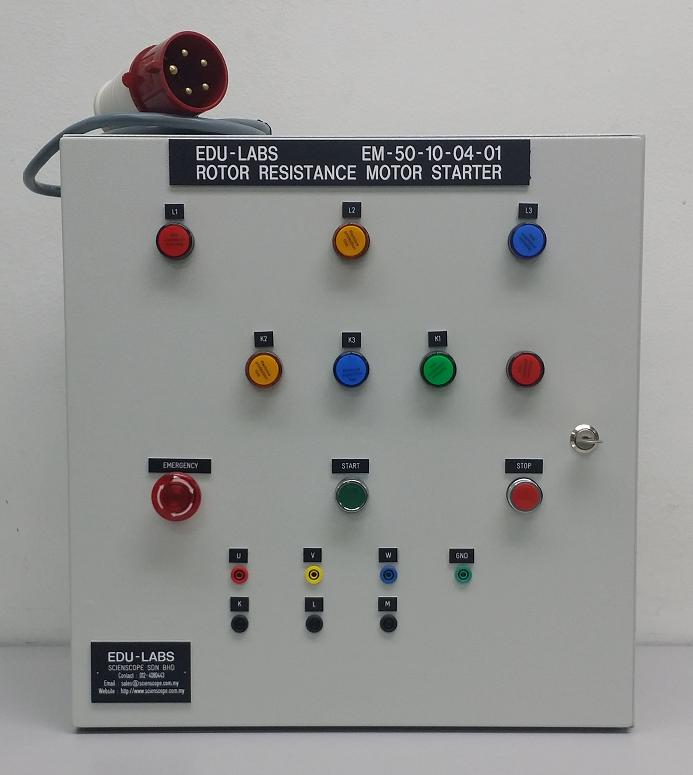
2.2.10 1 unit Rotor Resistance 7.5 kW (wired to terminal block 10 way, 600Vmax, 30A)
2.2.11 1 unit Soft Starter 7.5 kW/ 600V
2.2.12 3 units Current Transformer 30/5 A, 5VA CL3 c/w bracket
2.2.13 Terminal Block with marker: 60 ways, 600 V max, 10A
2.2.14 DIN Rail
2.3 Side panel complete with accessories specification:
2.3.1 6 units ventilation fan 100 mm x 100 mm (3 x left side and 3 x right side)
2.3.2 Incoming Industrial Socket Outlet: 32 A TPN industrial female socket
Note: Due to products continuous development process, layout and specification may change without prior notices.