
68HC11 Microcontroller Trainers MCT-68HC11Description
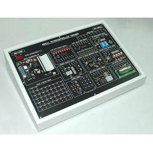
The MCT-68HC11 Microcontroller Trainer is designed specifically for educational, institutes and individuals who are interested in 68HC11 microcontroller. It includes a main frame with I/O ports and 9 built-in application modules and 2 optional application modules.
Specification
o The 68HC11 microcontroller board and 9 application modules are built-in the main frame.
o 8 x 5 rows of 2mm socket-type input/output ports are provided.
o DC power supplies of +5V(two each), -5V(two each), +12V(two each), -12V(two each) and GND (two each) are provided.
o The main frame enables future expansion of other application modules.
o The reset/restart button for the microcontroller should be easily accessible on the main trainer.
o Computer interfacing connectors of 68HC11 board are available.
o The dimension of the main frame is 330(L) x 260(W) x 110(H) mm.
o Input Voltage: AC 240V, 50Hz Accessories
o Power cord with a 13A fused mains plug at one end and a straight socket at the other.
o Relevant sets of 68HC11 technical data and programming manuals.
o RS-232 interfacing cable.
o Technical information, instruction manuals and circuit diagrams for the 68HC11 Microcontroller Trainer and Application Modules (including soft copy).
- Description
Description
Application Modules :
Module 1 : 8 Bits Data Display Module
This module consists of 8 input sockets and 8 buffers driven LEDs. It is used for monitoring the status of the each output port bit of the main frame.
Module 2 : 8 Bits Switch Input Module
This module consists of 8 toggle switches and 8 buffer driven output sockets. It is used for input of data to the input port of the main frame.
Module 3 : 7 Segment Display Module
This module consists of two 7-segment displays. The display is driven by a BCD to 7-segment driver IC through 2 multiplexing transistors.
Module 4 : Digital To Analog Converter Module
This module consists of an 8-bit D/A converter IC. Its output drives an inverting op amp with variable amplification factor.
Module 5 : DC Motor Control Module
This module consists of a small DC motor, 2 relays for direction control and an amplifier circuit for feeding PWM power to the DC motor.
Module 6 : Stepper Motor Control Module
This module consists of a 4-phase unipolar stepper motor driven through a buffer IC. 4 LEDs are connected to the stepper motor terminals so that phase status can be observed.
Module 7 : Keypad Module
This module consists of a 12 key keypad wired up in 3 x 4 matrix. It is an input device for the main frame.
Module 8 : LCD Display Module
Consists of a LCD panel (2 x 16 characters). Supply + 5V DC and ground terminals
Module 9 : Dot Matrix Display Module
This module consists of two 5 x 7 dot matrix LEDs. They are driven by buffers in a 10 x 7 matrix.
Module 10 : Car Park System Application Module (Optional)
This module consists of 2 sets of Infrared detectors, 2 motor driven gates, and four 7-segment displays. This module is designed for testing automatic car-park system software on a small scale.
Module 11 : Trigger Sensors And Alarm Circuit Module (Optional)
This module consists of 4 photo-coupled input devices and 2 transistors driven devices, a buzzer and a lamp.
Interface Software
o Interfacing software for Microsoft Windows 98, 2000, XP and above, including Winbug compiler, PC download utility software & Simulation Software
o The software for the 11 application modules are:
§ Motorola M68HC11 Assembler (as11)
§ 11 Example Projects Program (Assembly & Visual C) & Circuits
§ Softcopy in CD-ROM format and manual to be provide