
Main Switch Board Demonstrator (Single Feeder ACB 600A) EM-80-02-01-02Description
Request A Quotation
- Description
Description
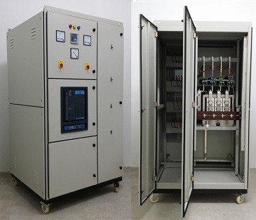
This is a standard industrial LV switchboard but specially adapted to function as a training unit. It enables switchgears, instrument and protective gears used in normal switchboard to be demonstrated and their functions explained. It is excellent practice units for students to study its circuitry, dismantle and reassemble component parts rewire. Compartment doors/covers are hinged and can be opened manually by finger-operated screws.
TECHNICAL SPECIFICATION
- Input: 415VAC, 100A, 3-phase, 50Hz
INCOMER PANEL
- Air Circuit Breaker 600A TP&N with overload and shunt trip coils
- Instruments :
- 1 No Ammeter, range 0 – 600A c/w Selector Switch
- 1 No Voltmeter, range 0 – 500V c/w Selector Switch
- 3 Nos 22mm Pilot Lamp (R/Y/B) Main Phase Lamp
- 1 No Power Factor Meter
- 3 Nos 600/5A Class 3, 15VA C/T Coil (for Ammeter)
- 1 No 600/5A Class 3, 15VA C/T Coil (for Power Factor Controller)
- 8 Nos MCB 1A, 6KA – for instruments control supply
- Protective Devices :
- 1 No Digital Combined IDMT Over Current & EFR
- 4 Nos 600/5A Class 10P10 C/T Coil (For IDMT, O/C & EFR)
OUTPUT PANEL
- 2 nos 100A MCCB TP&N
- 2 nos 200A MCCB TP&N
POWER FACTOR CORRECTION PANEL
- 1 No MCCB 60 Amp 3 Pole, 25 kA
- 1 No Power Factor Controller: 6 step
- 1 No 600/5A Class 3, 15VA C/T Coil (for P/F Controller)
- 6 Nos 10 Amp MCCB TP, 25kA
- 6 Nos 20 Amp Magnetic Contactor
- 6 Nos 5 kVAR Capacitor Bank (3 phase)
- 6 Nos 22mm Pilot Lamp – for Step Indicator Lamp
CONSTRUCTION
- Physical Size: Approx. 1300H X 1500W X 650D in mm
- Console: Heavy Sheet Steel
- Finish: Baked epoxy powder in matching grey & white
- Marking: Engraved / label printing legends
MANUAL
- Instruction Manual with Schematic Diagram
Note: Due to products continuous development process, layout and specification may change without prior notices.