
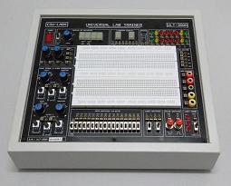
Analog & Digital Lab Trainer ADT-7000Description
- Description
Description
OVERVIEW
The ADT-7000 contains all of the functions required for studying and experimenting with analog electronics, digital electronics, telecommunication electronics etc. The ADT-7000 is a complete analog and digital training platform which is compact, lightweight and extremely durable.
APPLICATIONS
- Basic Electronics Training Courses
- Advanced Electronics Circuit Design
- Analog Circuit Experiments
- Digital Circuit Experiments
- Telecommunication Circuit Experiments
- Basic Logical Circuit Tracing
- Computer Interfacing Circuits
- Circuit Trouble Shooting
SPECIFICATIONS
- DC Power Supplies Module
Fixed Output: +5V/0.5A, -5V/0.5A, +12V/0.5A, -12V/0.5A
Variable Output: +0V ~ +23V/0.5A, -0V ~ -23V/0.5A
- AC Power Supplies Module
19V–15V–9V–0V–9V–15V-19V
- Function / Pulse Generator Module
Sine, Triangle and Square waveform output
Frequency range: 1Hz to 1MHz in 6 decades
With fine adjust, Amplitude and DC offset control
TTL Mode: 1Hz to 1MHz in 6 decades
Six frequency ranges:
1Hz to 10Hz
10Hz to 100Hz
100Hz to 1KHz
1KHz to 10KHz
10KHz to 100KHz
100KHz to 1MHz
Sine wave output: 0 to 12V peak to peak variable
Triangle wave output: 0 to 8V peak to peak variable
Square wave output: 0 to 22V peak to peak variable
- Removable Solderless Breadboard Module
Interconnected nickel plated with a total of 2200 tie points nickel plated contact, fitted all DIP sizes and all components with lead and solid wire in diameter of AWG #22-30 (0.3-0.8mm)
- Two Logic Output Switches Module
Provide two sets of logical output &
- Two Pulse Switches Module
Provide two sets of pulse output &
2 units push button switch contain switches debouncer for eliminating the bounce caused by switch from “open” to “close” or from “close“ to “open” position.
- 16-Bits Logic LED Indicators with buffer Module
Sixteen LED’s separate input terminals in three colors. (RED, Yellow & Green). The LED will be lighted up when input is at “HI Level”, and it will be turned off when it is at no input or at “LO Level”. Capable for Traffic Light Experiments.
- 16-Bits HI/LO Data Output Switches Module
16 units slide switches and corresponding output terminals. When switch is set at “down” position, the output is LO level; contrarily, it is to be HI level when setting at “up” position.
- TTL/CMOS Selection Switch
Select TTL or CMOS Mode for data switches
- Digital Display Module
Two digits 7-segment LED Display
Numerical designs and resultant display
- Speaker Module
8Ohm, 0.25W with Audio Amplifier
- Potentiometer Module
With 1K, 100K and 500K Ohm Potentiometers
- Adaptors Module
2 Channels 4mm Banana and 2 Channels BNC Adaptor
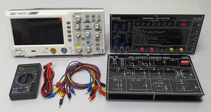
The ADT-7000 is shipped with a comprehensive CD Format Experiments Manual, Instruction Manual with Self Maintenance Guide and a power cord.
Power Supply : 240VAC, 50Hz (Fused Protected)
Dimensions : (W x D x H) 380 x 280 x 90mm
Weight : 3.5 kgs
EXPERIMENTS COVER
The ADT-7000 come with experiments manual (SOFTCOPY MANUAL ONLY WITHOUT COMPOENENTS & ACCESSORIES) to cover the following experiments topics:
(A) Analog Electronics Experiments Lists Cover In the Lab Manual:
Experiments 1: The Superposition Theorem
Experiments 2: Capacitors in Voltage – Divider Networks
Experiments 3: Operational Amplifier – The Inverting Amplifier
Experiments 4: Operational Amplifier – The Non inverting Amplifier
Experiments 5: Operational Amplifier – The Comparator
Experiments 6: Operational Amplifier – The Summing Amplifier
Experiments 7: The Common – Base Amplifier Structure
Experiments 8: The Common – Emitter Amplifier Structure
Experiments 9: The Common – Collector Amplifier Structure
Experiments 10: The Op Amp Differentiator
Experiments 11: The Op Amp Integrator
Experiments 12: The RC Phase Shift Oscillator
Experiments 13: The As table Multivibrator
Experiments 14: The Schmitt Trigger
Experiments 15: The As table Multivibrator
Experiments 16: The D/A Converter
Experiments 17: The A/D Converter
(B) Digital Electronics Experiments Lists Cover In the Lab Manual:
Experiments 1: Fundamental Logic Gate – AND, OR, NOT
Experiments 2: Fundamental Logic Gate – NAND, NOR, XOR
Experiments 3: Applications of Boolean Algebra
Experiments 4: De Morgan’s Law (I)
Experiments 5: De Morgan’s Law (II)
Experiments 6: Diode Resistor Logic – AND
Experiments 7: Exclusive OR
Experiments 8: Exclusive NOR
Experiments 9: Demultiplexer
Experiments 10: Synchronous Up – Counter
Experiments 11: Synchronous Down – Counter
Experiments 12: The Schmitt Trigger
Experiments 13: Oscillator – Counter
Note: Due to products continuous development process, layout and specification may change without prior notices.