Product Category
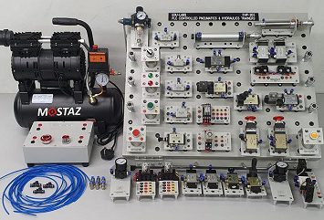
- Pneumatics & Electro-Pneumatics Training System
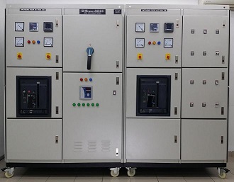
- Main Switchboard & Feeder Pillar Training System
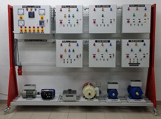
- Motor Control & Starter Training System
- Switchboard & Feeder Pillar Training System
- Power Transmission & Distribution Training System
- Electrical Machines Training System
- Consumer Electronics Training System
- Electronics & Electricity Training System
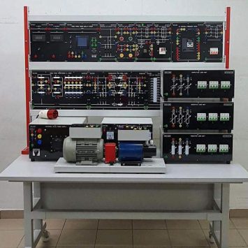
- Electrical Installation Technology Training System
- Electrical & Power Training System
- Hydraulics & Electro-Hydraulics Training System
- Green Technology Training System
- Microprocessor & Microcontroller Training System
- Mechanical Training System
- Mechatronics Training System
- PCB Prototype Machine
- Process Control & Instrumentation Training System
- Power Electronics Training System
- Programmable Logic Controller Training System
- Telecommunication Training System
- Temperature Monitoring System - TECSYSTEM
- Test & Measuring Instruments
- Robotics & Automation Training System

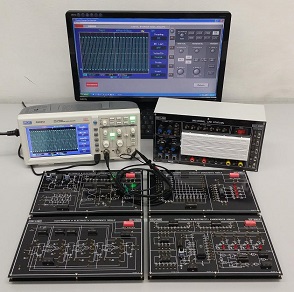
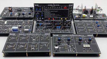
Digital Communication Trainers TC-6000
Description
Features
1. Design and implementation of line code encoder and decoder.
2. Design and implementation of PWM and PCM modem.
3. Design and implementation of DM and ADM modem.
4. Design and implementation of ASK, FSK, PSK and QPSK modulation and demodulation.
Objectives
1. To understand the basic theory of digital communication system.
2. Design and implementation ability training of digital modem.
3. To understand the applications of balanced modulator circuit.
4. To understand the applications of digital modem.
TC-6000-01: Line Code Encoder and Decoder Experiments Module
Lab 1: Line Code Encoder
Experiment 1: Unipolar and Bipolar NRZ Signal Encoder (Signal: TTL, Data Rate: 1 kbps ~ 4 kbps)
Experiment 2: Unipolar and Bipolar RZ Signal Encoder (Signal: TTL, Data Rate: 1 kbps ~ 2.5 kbps, CLK: 2 kHz ~ 5 kHz)
Experiment 3: AMI Signal Encoder (Signal: TTL, Data Rate: 50 bps ~ 250 bps, CLK: 100 Hz ~ 500 Hz)
Experiment 4: Manchester Signal Encoder (Signal: TTL, Data Rate: 100 bps ~ 400 bps, CLK: 200 Hz ~ 800 Hz)
Lab 2: Line Code Decoder
Experiment 1: Unipolar and Bipolar NRZ Signal Decoder (Signal: TTL, Data Rate: 1 kbps ~ 4 kbps)
Experiment 2: Unipolar and Bipolar RZ Signal Decoder (Signal: TTL, Data Rate: 1 kbps ~ 2.5 kbps, CLK: 2 kHz ~ 5 kHz)
Experiment 3: AMI Signal Decoder (Type of Signal: TTL, Data Rate: 50 bps ~ 250 bps, CLK: 100 Hz ~ 500 Hz)
Experiment 4: Manchester Signal Decoder (Signal: TTL, Data Rate: 100 bps ~ 400 bps, CLK: 200 Hz ~ 800
TC-6000-02: PWM (Pulse Width) Modulation and Demodulation Experiments Module
Lab 3: Pulse Width Modulator
Experiment 1: UA741 PWM Circuit (Carrier Signal: 1.5 kHz ~ 2 kHz; Audio Signal Frequency: 500Hz)
Experiment 2: LM566 PWM Circuit (Carrier Signal: 5 kHz ~ 10 kHz; Audio Signal Frequency: 1 kHz)
Lab 4: Pulse Width Demodulator
Experiment 1: PWM Demodulation Circuit (Carrier Signal: 5 kHz ~ 6 kHz; Audio Signal Frequency: 500 Hz ~ 700 Hz)
TC-6000-03: PCM (Pulse Code) Modulation and Demodulation Experiments Module
Lab 5: PCM Modulator
Experiment 1: PCM Modulator (Built-in Sample Frequency: 8 kHz, Built-in Operation Frequency: 2048 kHz, Audio Signal: 100 Hz ~ 2 kHz)
Lab 6: PCM Demodulator
Experiment 1: PCM Demodulator (Built-in Sample Frequency: 8 kHz, Built-in Operation Frequency: 2048 kHz, Audio Signal: 100 Hz ~ 2 kHz)
TC-6000-04: Delta Modulation and Demodulation Experiments Module
Lab 7: Delta Modulator
Experiment 1: Delta Modulator (Type of Sample Signal: TTL CLK, Sample Frequency: 32 kHz ~ 256 kHz, Audio Signal: 1 kHz ~ 3 kHz)
Lab 8: Delta Demodulator
Experiment 1: Delta Demodulator (Type of Sample Signal: TTL CLK, Sample Frequency: 32 kHz ~ 256 kHz, Audio Signal: 1 kHz ~ 3 kHz)
TC-6000-05: Adaptive Delta Modulation and Demodulation Experiments Module
Lab 9: Adaptive Delta Modulator
Experiment 1: Adaptive Delta Modulator (Type of Sample Signal: TTL CLK, Sample Frequency: 32 kHz ~ 128 kHz, Audio Signal: 500 Hz ~ 1 kHz)
Lab 10: Adaptive Delta Demodulator
Experiment 1: Adaptive Delta Demodulator (Type of Sample Signal: TTL CLK, Sample Frequency: 64 kHz ~ 256 kHz, Audio Signal: 500 Hz ~ 1 kHz)
TC-6000-06: ASK (Amplitude-Shift Keying) Modulation and Demodulation Experiments Module
Lab 11: Amplitude-Shift Keying Modulator
Experiment 1: ASK Modulation Circuit (Carrier Signal: 20 kHz ~ 100 kHz; Modulation Signal Frequency: 1 kHz ~ 10 kHz)
Lab 12: Amplitude-Shift Keying Demodulator
Experiment 1: ASK Non-coherent Detection Circuit (Carrier Signal: 20 kHz ~ 100 kHz; Modulation Signal Frequency: 1 kHz ~ 10 kHz)
Experiment 2: ASK Coherent Detection Circuit (Carrier Signal: 20 kHz ~ 100 kHz; Modulation Signal Frequency: 1 kHz ~ 10 kHz)
TC-6000-07: FSK (Frequency-Shift Keying) Modulation and Demodulation Experiments Module
Lab 13: Frequency-Shift Keying Modulator
Experiment 1: FSK Modulation Circuit (Space Signal: 1370 Hz; Mark Signal: 870 Hz; Data Signal: 200 Hz ~ 5 kHz)
Lab 14: Frequency-Shift Keying Demodulator
Experiment 1: FSK Demodulation Circuit (Space Signal: 1370 Hz; Mark Signal: 870 Hz; Data Signal: 200 Hz ~ 5 kHz)
TC-6000-08: PSK (Phase-Shift Keying) Modulation and Demodulation Experiments Module
Lab 15: Phase-Shift Keying Modulator
Experiment 1: PSK Modulation Circuit (Carrier Signal: 100 kHz; Data Rate: 200 bps; Data Signal: 100 Hz ~ 1kHz)
Lab 16: Phase-Shift Keying Demodulator
Experiment 1: PSK Demodulation Circuit (Carrier Signal: 100 kHz; Data Rate: 400 bps ~ 1000 bps; Data Signal: 100 Hz ~ 1kHz)
TC-6000-09: QPSK (Quadrature Phase-Shift Keying) Modulation and Demodulation Experiments Module
Lab 17: QPSK Modulator
Experiment 1: Bit-splitter Circuit (Data Rate: 100 bps ~ 1000 bps)
Experiment 2: QPSK Modulation Circuit (Carrier Signal: 20 kHz; Data Rate: 1000bps)
Lab 18: QPSK Demodulator
Experiment 1: Signal-square and PLL Circuit (Carrier Signal: 20 kHz; Data Rate: 1000 bps)
Experiment 2: QPSK Demodulation Circuit (Carrier Signal: 20 kHz; Data Rate: 1000 bps)