

ABOUT US
Welcome To Scienscope Sdn Bhd
Established since 2000, SCIENSCOPE SDN BHD is Malaysia’s leading solution provider for technical education training and laboratories equipment.
With our in-house assemble and with 100% quality inspection and quick response technical support, we ensure customers to receive the desired products with satisfaction. We are looking forward to being of assistance to you.
0
+
Products Available
Wide range of training and laboratories products available
Feature Products
Product Categories
-
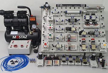
Pneumatics & Electro-Pneumatics Training System
2 products -
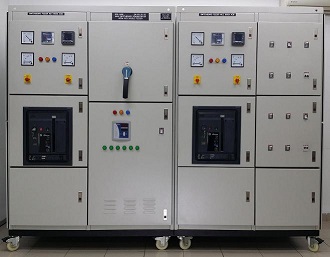
Main Switchboard Training System
10 products -
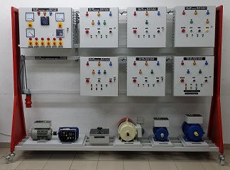
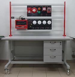
Motor Control & Starter Training System
8 products -
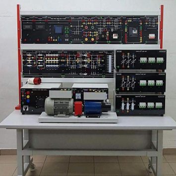
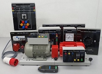
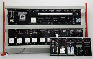
Power System Training System
5 products -
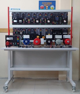
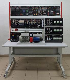
Electrical Machines Training System
35 products -
Consumer Electronics Training System
13 products -
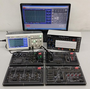
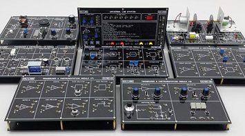
Electronics & Electricity Training System
13 products -
Electrical Installation Technology Training System
2 products -
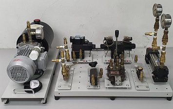
Hydraulics & Electro-Hydraulics Training System
19 products -
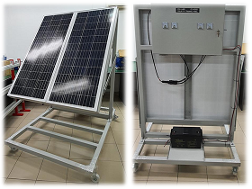
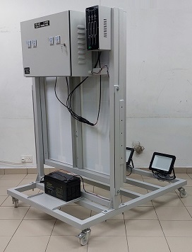
Green Technology Training System
1 product