Product Category
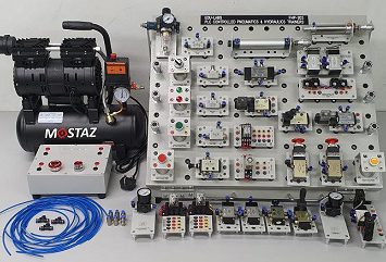
- Pneumatics & Electro-Pneumatics Training System
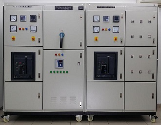
- Main Switchboard & Feeder Pillar Training System
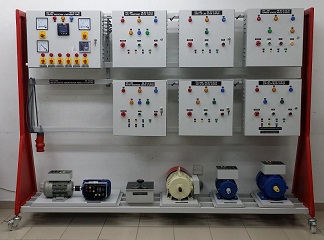
- Motor Control & Starter Training System
- Switchboard & Feeder Pillar Training System
- Power Transmission & Distribution Training System
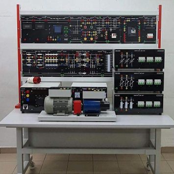
- Electrical Machines Training System
- Consumer Electronics Training System
- Electronics & Electricity Training System
- Electrical Installation Technology Training System
- Electrical & Power Training System
- Hydraulics & Electro-Hydraulics Training System
- Green Technology Training System
- Microprocessor & Microcontroller Training System
- Mechanical Training System
- Mechatronics Training System
- PCB Prototype Machine
- Process Control & Instrumentation Training System
- Power Electronics Training System
- Programmable Logic Controller Training System
- Telecommunication Training System
- Temperature Monitoring System - TECSYSTEM
- Test & Measuring Instruments
- Robotics & Automation Training System

Universal Lab Trainers ULT-3000
Description
OVERVIEW
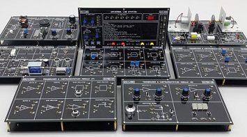
The ULT-3000 contains all of the functions required for studying and experimenting with analog electronics, digital electronics, communication electronics etc. The ULT-3000 is a complete analog and digital training platform which is compact, lightweight and extremely durable.
EXPERIMENTS COVER
The ULT-3000 come with experiments manual (SOFTCOPY MANUAL ONLY NO COMPOENENTS) to cover the following experiments topics:
(A) Digital Electronics Experiments Lists Cover in the Lab Manual:
- Fundamental Logic Gate – AND, OR, NOT
- Fundamental Logic Gate – NAND, NOR, XOR
- Application Of Boolean Algebra
- De Morgan’s Law (I)
- De Morgan’s Law (II)
- Diode Resistor Logic – AND
- Exclusive OR Using Basic Logic Gate
- Exclusive NOR Using Basic Logic Gate
- Demultiplexer – Using The 74138 IC
- Synchronous Up – Counter
- Synchronous Down – Counter
- The Schmitt Trigger
- Oscillator – Using CMOS
(B) Analog Electronics Experiments Lists Cover In the Lab Manual :
- The Superposition Theorem
- Capacitors in Voltage – Divider Networks
- Operational Amplifier – The Inverting Amplifier
- Operational Amplifier – The Non Inverting Amplifier
- Operational Amplifier – The Comparator
- Operational Amplifier - The Summing Amplifier
- The Common – Base Amplifier Structure
- The Common – Emitter Amplifier Structure
- The Common – Collector Amplifier Structure
- The Op Amp Differentiator
- The Op Amp Integrator
- The RC Phase Shift Oscillator
- The Schmitt Trigger
- The Astable Multivibrator
- The D/A Converter
- The A/D Converter
APPLICATIONS
- Basic Electronics Training Courses
- Advanced Electronics Circuit Design
- Analog Circuit Experiments
- Digital Circuit Experiments
- Basic Logical Circuit Tracing
- Computer Interfacing Circuits
- Circuit Trouble Shooting
SPECIFICATION
1. DC Power Supplies Module
- Fixed Output: +5V/1A, -5V/0.5A, +12V/0.5A, -12V/0.5A
- Variable Output: +0V ~ +25V/1A, -0V to -25V/0.5A
- All power supplies are short circuit protected.
2. AC Power Supplies Module
- 19V–15V–9V–0V–9V–15V-19V
3. Function Generator (2 Channels) & Clock Generator (2 Channels)
- Sine, Triangle and Square waveform output
- Frequency range : 1Hz to 1MHz in 6 decades
- With fine adjust, Amplitude and DC offset control
- Clock output 1Hz to 1MHz in 6 decades
- Six frequency ranges:
- 1Hz to 10Hz
- 10Hz to 100Hz
- 100Hz to 1KHz
- 1KHz to 10KHz
- 10KHz to 100KHz
- 100KHz to 1MHz
- Sine wave output: 0 to 12V peak to peak variable
- Triangle wave output: 0 to 8V peak to peak variable
- Square wave output: 0 to 12V peak to peak variable
4. Solderless Breadboard Module
- Interconnected with 2712 tie points nickel plated contact, fits all components with DIP sizes and solid wire AWG#22-30 (0.30.8mm).
5. TTL/CMOS Selection Switch
- Select TTL (+5V) or CMOS (12V) Mode for data switches
6. 2-Single Shot Pulse Module
- 2 units push-buttons debouncer switches
- 80µS Positive & Negative Pulse
7. Two digits of 7-segment LED Display Module
- Output numerical displays
- Segment Identification
8. 16-bit LED Indicators with buffer Module
- Sixteen LED's separate input terminals.
- The LED lighted up when input at "HI level", and turned off when no input or at "LO level"
9. 16-bit HI/LO Data Output Switches Module
- Sixteen slide switches’ separate input terminals.
- When slide switch set at "down" position, the output is LO level; it will be HI level while setting at "up" position.
10. 3-State Logic Probe Module
- HI, Float & LO Level LED Logic Indicator
11. Speaker Module
- 8 Ohm, 0.25W With Buffer
12. Digital DC Volt Meter
- 4 ½ Digits LED display
- Four voltage ranges :
- 0V to 199.9VDC
- 0V to 19.99VDC
- 0V to 1.999VDC
- 0V to 199.9mVDC
- Input Impedance: 10Mohm for any range
13. Adaptors Interface Module
- 2mm & 4mm Adaptor Interface Socket to turn pins socket
The ULT-3000 is shipped with a comprehensive Experiments & Instruction manaul in CD Format a power cord.
Power Supply : 240VAC, 50Hz (Fused Protected)
Dimensions : (W x D x H) 310 x 260 x 90mm
Weight : 3.5 kgs